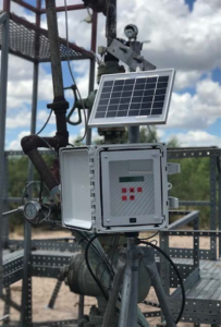
Controller System
- Designed with the operator in mind
- Stand Alone or Modbus capable
- Low power and maintenance
- Plunger Lift SCADA Page coming soon!
- One model for all applications
- Timer
- Auto Adjust-Time
- Pressure Modes (transducers needed, sold separately)
- Load Factor–Open
- Pressure Open–TBG, CSG, Line
- CSG Upturn–After Flow
- Hi-Lo Controller
- Custom Applications available upon request
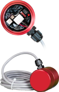
Arrival Sensor
- 3D Arrival Sensor
- Detects in 3 Axis, X, Y, and Z
- Class 1 Division 2 Certified
- Works with all major MFG controllers and SCADA
- 5 volt–28 volt systems
- Screw Cap with o-ring to deter moisture
- Test LED light in every unit
- Test switch to enable
- Sensitivity Adjustment in every unit
- Explosion Proof Container Available
Gas Assisted Plunger Lift
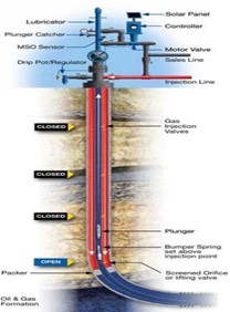
- Gas Assisted Plunger Lift (GAPL) is a hybrid method of gas lift that utilizes a plunger to increase efficiency of lift gas
- Can help eliminate common GL inefficiencies
- Over Injection
- Liquid Slippage
- Paraffin Formation (cooling effect)
- Plunger provides a mechanical interface between gas & liquid
- Bypass plungers will not cause valve transfer issues and are appropriate tool for GAPL
- May delay or eliminate the need to pull TBG and redesign Gas Lift System as well conditions change
GAPL Benefits
- Interface provides full sweep of liquids in production string, where slippage typically still occurs
- Maximizes fluid recovery (oil)
- Paraffin Solidifies in upper end of production string where velocities are highest.
- Cooling effect occurs from injection point around GL valves, interrupting operation and hindering production. Plunger alleviates issue.
- Solids control (Scale and Iron Sulfates). Keeping tubing clear.
- Lower BHFP, lower drawdown will yield net production gains/uplift
- As this happens, have the ability to lower injection rates or eliminate injection Release compression, etc.
GAPL Candidate Selection
- Wells that produce up to 350-500Bblsliquids per day, depending on tubing size (2 3/8” 350BblsMax & 2 7/8” 500BblsMax)
- GLR equivalent to 350-500Bbls/750Mcf/d-1MMcf/d Gross Gas
- Depends on fluid cut (50%+ Oil = lighter weight = larger pool of well candidates)
- Have seen success with lower GLR
- Line Pressure has to be considered
- GL Designs with GAPL as long-term vision, can be more effective. Set SN just above bottom valve or screened orifice. A packer-less application can allow you to inject around EOT and right-size compression through the life of the well.
- Stand-alone Bypass PL (no Gas Lift assistance) can operate with up to 400 Bls/1MMcf/d, depending on tubing size, line pressure in field


